Anaes · Ultrasound-guided peripheral nerve blocks
Ultrasound physics and sonoanatomy for regional anaesthesia
Also known as Sonoanatomy · Ultrasound-guided regional anaesthesia · USGRA basics · Ultrasound physics for regional anaesthesia · In-plane and out-of-plane needle technique · Tissue echogenicity and anisotropy · Dynamic needle tip positioning
Ultrasound-guided regional anaesthesia (USGRA) directs a block needle onto a target nerve under real-time imaging so that local anaesthetic is deposited precisely while intraneural and intravascular injection are avoided. Its mastery rests on the physics by which a piezoelectric crystal builds an image from echoes, the resolution-penetration trade-off of probe frequency, the characteristic echogenic appearance of nerve, vessel, muscle and bone, the discipline of the in-plane and out-of-plane needle approaches and dynamic needle tip positioning, and the cardinal rule of always knowing where the needle tip is.
On this page & tools
Your progress
Saved locally on this device.
8 MCQs with explanations
Target exams
Red flags
Overview
Ultrasound-guided regional anaesthesia (USGRA) is the contemporary standard for peripheral nerve blockade: the operator images the target nerve and the surrounding anatomy in real time, advances a needle under direct vision, watches the local anaesthetic spread around the nerve, and so delivers the drug precisely while avoiding intraneural and intravascular injection[1]. Before ultrasound, blocks were performed by eliciting paraesthesia or by using a nerve stimulator, both of which inferred the nerve's position indirectly. The move to ultrasound did not change the anatomy or the local anaesthetic — it changed the operator's eyes, and with them the success rate, the dose and the safety of the block[1][7].
Mastery of USGRA rests on three layers of knowledge. The first is the physics by which a piezoelectric crystal turns an electrical signal into a pulse of sound and the returning echoes back into an electrical signal, and how the frequency of that pulse sets the resolution-penetration trade-off that governs every probe choice[2]. The second is the sonoanatomy: the characteristic echogenic appearance of nerve, vessel, muscle, fat, fascia and bone, and the artefacts (anisotropy, shadowing, reverberation) that can fool the operator[2][3]. The third is the technique: the in-plane and out-of-plane needle approaches, the discipline of always knowing where the needle tip is, the optimisation of the machine, and the ergonomics that let the operator perform a precise hand-eye task safely[4][8]. This topic covers all three in the depth the fellowship examination expects, and closes with the safety framework and the comparison with nerve stimulation that the modern regional anaesthetist must articulate[5][7].
The piezoelectric principle and the generation of sound
The ultrasound transducer is the heart of the machine. Its functional element is a piezoelectric crystal — most commonly a lead zirconate titanate ceramic — that converts electrical energy into mechanical energy and back again. When a voltage is applied across the crystal it deforms (it contracts or expands), and if the voltage alternates rapidly the crystal vibrates, emitting a pulse of high-frequency sound into the tissue. When the returning echo vibrates the crystal in turn, the piezoelectric effect generates a voltage that the machine can measure. The same crystal is therefore both the loudspeaker and the microphone, and a single transducer houses an array of many such crystals (the linear array) that are fired in sequence or in groups to sweep a beam across the field[2].
This reciprocal conversion is the reason the modality is called ultrasound: the frequencies used, between roughly two and fifteen megahertz, are far above the twenty kilohertz upper limit of human hearing. The choice of frequency is the single most important decision the operator makes, because it sets the resolution-penetration trade-off that defines what can be seen and how deeply[1][2].
Frequency, wavelength and the resolution-penetration trade-off
Sound is a wave, and like any wave it has a frequency (the number of cycles per second, in hertz) and a wavelength (the distance between successive peaks). The two are linked by the speed of sound in the medium: wavelength equals the speed of sound divided by the frequency. In soft tissue the speed of sound is, by convention, taken to be a constant 1540 metres per second, because the machine's software assumes this value to calculate depth from echo time. Using that constant, the wavelength of a ten-megahertz beam is 1540 divided by ten million, or about 0.154 millimetres (154 micrometres); the wavelength of a five-megahertz beam is about 0.31 millimetres; and the wavelength of a two-megahertz beam is about 0.77 millimetres[2].
The wavelength matters because it sets the best possible resolution the system can achieve: two structures closer together than about one wavelength cannot be reliably distinguished as separate. A short wavelength (a high frequency) therefore means fine resolution, and a long wavelength (a low frequency) means coarse resolution. But there is a price. As sound travels through tissue a fraction of its energy is absorbed and converted to heat, and the rate of absorption rises with frequency — a high-frequency beam loses energy quickly and penetrates only a short distance, while a low-frequency beam penetrates deeply but at the cost of resolution. This is the resolution-penetration trade-off, and it is the physical basis of every probe choice in regional anaesthesia[2][1].
High-frequency probes: resolution at the cost of penetration
A high-frequency linear probe (ten to fifteen megahertz, sometimes up to eighteen for specialist superficial work) produces a short wavelength and therefore fine axial and lateral resolution. It is the probe of choice for superficial nerves close to the skin: the interscalene and supraclavicular brachial plexus (two to four centimetres deep), the axillary and midforearm nerves, the femoral nerve at the inguinal crease, and the truncal blocks (transversus abdominis plane, rectus sheath) where the target is within a few centimetres of the probe. Its weakness is penetration: the high-frequency beam is absorbed within five to six centimetres, so deeper targets are poorly seen or invisible, and the patient's subcutaneous fat (which absorbs and scatters sound) further shortens the effective reach. A high-frequency probe used on a deep target gives a dark, noisy image in which the nerve cannot be identified[2][1].
Low-frequency probes: penetration at the cost of resolution
A low-frequency curvilinear probe (two to five megahertz) produces a long wavelength and therefore coarser resolution, but it penetrates deeply — ten centimetres or more. It is the probe of choice for deep nerves: the sciatic nerve in the subgluteal or anterior approach, the lumbar plexus (psoas compartment), the neuraxial structures for spinal and epidural imaging, and the transversus abdominis plane in the obese patient. Its weakness is resolution: small superficial nerves are poorly defined, and the coarser beam means two adjacent small structures may merge into one indistinct blob. Some blocks (the infraclavicular brachial plexus, the popliteal sciatic in a larger patient) sit at the boundary where either probe could be argued for, and the operator judges the depth of the specific target[2][1].
Choosing the probe
The rule is simple: use the highest-frequency probe that still reaches the target at adequate brightness. For a superficial nerve this is unambiguous — a high-frequency linear probe. For a deep nerve the operator accepts the resolution loss of a low-frequency curvilinear probe as the price of being able to see the target at all. The mistake to avoid is the opposite extremes: a high-frequency probe on a deep target (everything is dark) and a low-frequency probe on a superficial target (everything is blurry). Modern broadband probes and the ability to switch frequency bands within a single probe have softened this choice, but the underlying physics is unchanged[1][2].
[1]How the image is built: the pulse-echo principle
The image on the screen is built one line at a time from the pulse-echo principle. The transducer emits a brief pulse of sound — a small number of cycles, typically two — then waits in silence and listens for the echoes. The pulse travels into the tissue at 1540 metres per second; wherever it meets an interface between tissues of different acoustic properties, a fraction of its energy is reflected back toward the probe, and the rest continues deeper[2].
Two pieces of information are extracted from each returning echo. The first is the time delay between emitting the pulse and receiving the echo. Because the speed of sound is assumed constant at 1540 metres per second, the machine converts the time delay into a depth: an echo returning after a certain microseconds corresponds to a reflector at half that acoustic distance (half because the sound travels out and back). The deeper the reflector, the longer the echo takes to return. The second piece of information is the amplitude (strength) of the echo: a strong reflection gives a bright dot, a weak one a faint dot[2].
The machine repeats this send-and-receive cycle for each crystal (or group of crystals) across the array, building up a vertical line of dots for each beam position. When the array is swept, the lines are placed side by side to form a two-dimensional greyscale image — this is B-mode, brightness mode, the standard real-time image. The machine repeats the whole sweep twenty to sixty times per second (the frame rate), producing a moving, real-time image in which the operator can watch the needle advance and the local anaesthetic spread. The frame rate depends on the depth setting (deeper images take longer, because the machine must wait longer for the last echo) and the width of the field; increasing either lowers the frame rate[2].
Axial resolution: telling two objects apart along the beam
Axial resolution is the minimum separation at which two objects lying one behind the other along the beam direction can be shown as two distinct echoes rather than one. It is determined by the spatial pulse length — the physical length of the pulse in the tissue — and equals half the spatial pulse length. A pulse of two cycles at ten megahertz has a spatial pulse length of two wavelengths, so its axial resolution is one wavelength, about 0.15 millimetres; the operator can distinguish two reflectors 0.15 millimetres apart. Shorter pulses and higher frequencies (shorter wavelengths) improve axial resolution, which is why high-frequency probes resolve fine detail along the beam[2].
Lateral resolution: telling two objects apart across the beam
Lateral resolution is the minimum separation at which two objects lying side by side, perpendicular to the beam, can be shown as two distinct echoes. It is determined by the beam width: a narrow beam resolves closely spaced objects, a wide beam smears them together. The beam is narrowest at the focal zone, which the operator sets (or the machine auto-focuses) to the depth of the target. Modern linear arrays use electronic focusing — firing the outer crystals slightly before the inner ones to bend (focus) the beam to a chosen depth — and the focus should be set at or just below the nerve to maximise lateral resolution where it matters. A beam that is too wide at the target's depth makes a small nerve look larger and blurrier than it is[2].
[1]Interaction of sound with tissue
When a pulse of sound meets a boundary between two tissues, four things can happen to it, and each underlies a feature of the image. [1]
Reflection
At an interface between two tissues that differ in acoustic impedance (the product of tissue density and the speed of sound in that tissue), a fraction of the sound is reflected back toward the probe and the rest is transmitted deeper. The greater the mismatch in acoustic impedance, the greater the fraction reflected. Soft tissue to soft tissue interfaces (muscle to fat, nerve to surrounding connective tissue) reflect a modest fraction, giving the visible greyscale texture of the image. A soft tissue to bone interface reflects almost everything (bone has a very high acoustic impedance), which is why bone appears as a bright line — but because almost nothing is transmitted, nothing is seen behind it, producing the dark acoustic shadow. A soft tissue to air interface reflects essentially all the sound (air has a very low acoustic impedance), which is why gel must couple the probe to the skin and why air in the tissues (emphysema, bowel gas) ruins the image[2][3].
Scattering
When the beam meets a structure smaller than its wavelength, or a rough interface, the sound is scattered in many directions rather than reflected cleanly back. This scattering, returning from within a homogeneous tissue like the liver or muscle, produces the speckle pattern — the fine granular texture that gives tissue its characteristic greyscale appearance. The speckle is not a true image of individual scatterers; it is an interference pattern, but it is diagnostically useful because different tissues produce different speckle textures[2].
Absorption
As the beam travels, a fraction of its energy is absorbed by the tissue and converted to heat. This is the principal cause of beam attenuation (loss of energy with depth), and it rises with frequency — the physical basis of the penetration limit of high-frequency probes. Absorption is also the safety concern behind the thermal index (below). Deeper structures are imaged through more absorbing tissue, so the returning echoes are weaker; the machine compensates for this with time gain compensation, amplifying the echoes from greater depths so that the image is of roughly uniform brightness from top to bottom[2].
Refraction
When a beam crosses an interface between two tissues in which the speed of sound differs, and it does so at an angle, the beam bends — just as light bends at a water surface. This refraction can displace the apparent position of a deep structure from its true position, a pitfall the operator should be aware of, though it is less prominent in regional anaesthesia than in echocardiography. Refraction is also the basis of the acoustic lens built into the face of many probes, which focuses the beam as it leaves the crystal[2].

The appearance of tissues: reading the sonogram
Reading the sonogram is the core skill of sonoanatomy. Each tissue has a characteristic echogenicity — how bright or dark it appears — and a characteristic texture, and recognising these is what lets the operator identify the nerve and the structures around it. Echogenicity is described in relative terms: hyperechoic means brighter than the surrounding tissue, hypoechoic means darker, and anechoic means black (no internal echoes)[1][9].
Nerve
A peripheral nerve seen in transverse section is a rounded, oval or triangular bundle with a honeycomb appearance: small hypoechoic (dark) round areas — the individual nerve fascicles — set within a hyperechoic (bright) background of connective tissue, the epineurium and perineurium. The whole bundle is itself enclosed in a bright rim. This honeycomb pattern is the signature of nerve, and ultra-high-frequency imaging has confirmed that the dark fascicles seen on ultrasound correspond to the true fascicular structure seen on histology[9]. Two cautions apply. First, the appearance depends on the nerve and the probe: a large mixed nerve like the sciatic shows the honeycomb clearly, but a small pure sensory nerve may appear simply hypoechoic (dark) and can be mistaken for a vessel or a fascial plane. Second, nerves are anisotropic (below): they brighten when the beam is perpendicular and darken when angled, so the same nerve can look bright in one scan and dark in the next[2][9].
Tendon
A tendon in transverse section appears as a bright round or oval structure with a fibrillar internal pattern — the closely packed collagen fibre bundles — and like nerve it is anisotropic. Tendon is the structure most easily confused with nerve, because both are bright and fibrillar. The two are distinguished by tracing the structure along its course: a tendon inserts on a bone and changes into muscle, whereas a nerve branches and travels in a neurovascular bundle. In addition, a tendon is brighter and more tightly fibrillar than a nerve, and on contracting the muscle the tendon moves while the nerve does not[2].
Artery
An artery appears as a round or oval anechoic (black) structure — fluid does not reflect sound internally — with a visibly pulsatile wall, that is, it expands and contracts with each cardiac cycle, and it is not compressible by gentle probe pressure. Colour Doppler shows pulsatile flow within it (the colour flickers on and off with the pulse). An artery has a thicker, more echogenic wall than a vein. The cardinal point is that an artery is not compressible: pressing the probe down does not collapse it, whereas a vein collapses readily. This distinction is critical, because mistaking an artery for a nerve and injecting into it causes local-anaesthetic systemic toxicity[1][3].
Vein
A vein also appears as a round or oval anechoic structure, but unlike an artery it is readily compressible — gentle pressure on the probe collapses it completely — and it varies in size with respiration (it enlarges with a Valsalva manoeuvre or in the head-down position, as venous return is impeded). Colour Doppler shows low-velocity flow that augments with distal compression. The compressibility test is the practical bedside discriminator between a vein and a nerve or a small artery: a structure that disappears under probe pressure is a vein; one that persists is not[1][3].
Fat
Subcutaneous fat appears hypoechoic (dark) with a loose, slightly heterogeneous texture and scattered bright connective-tissue septa. It is the tissue through which the beam must pass to reach deeper structures, and because it both scatters and absorbs sound, a thick fat layer degrades the image of anything beneath it — a particular problem in obesity, and a reason deeper targets in obese patients demand a lower-frequency probe. Fat is often the background against which a nerve's honeycomb stands out[2].
Muscle
Skeletal muscle appears hypoechoic (dark) with bright (hyperechoic) linear striations — the perimysium and the fascial planes between and within muscles. The bright fascial planes are important landmarks in sonoanatomy: nerves commonly lie in the plane between two muscles (the interscalene plane, the transversus abdominis plane), and identifying the plane is often the first step to finding the nerve. Muscle is therefore read both for its own appearance and for the fascial architecture it provides[1][2].
Bone
Bone, because of its very high acoustic impedance, reflects almost all the incident sound and transmits almost none. It therefore appears as a bright (hyperechoic) continuous line at its surface, beneath which is a dark acoustic shadow where no sound penetrates and nothing can be seen. This is useful as a landmark (a rib, a transverse process, the humerus identifies the region) but it also means that any nerve lying behind bone is invisible to ultrasound — the sciatic nerve deep to the gluteal muscles can be hard to see if the beam passes through the greater trochanter, for example[2][3].
Fascia and connective tissue
Fascia appears as a thin bright (hyperechoic) line — the bright interface between the hypoechoic muscle on either side. Fascial planes are the highways along which injected local anaesthetic tracks, and a block is often described by the fascial plane it targets (the transversus abdominis plane block, the erector spinae plane block). Identifying the fascial plane is often more important than identifying a discrete nerve, because the local anaesthetic spread within the plane is what produces the block[1][2].
Identifying and confirming the nerve
A peripheral nerve is identified by a convergence of evidence, never by a single feature in isolation. The operator looks for the honeycomb texture in transverse section, confirmed by scanning longitudinally (where the nerve shows continuous parallel fibrillar lines representing the fascicles running along its length), by tracing the structure proximally and distally along its expected anatomical course, and by its position relative to the known surrounding structures — the vessels (confirmed by Doppler), the fascial planes, and the bone landmarks. A nerve is distinguished from a tendon by tracing (a tendon reaches a bone, a nerve enters a neurovascular bundle and branches), from a vessel by Doppler and compressibility, and from a fascial plane by its discrete rounded cross-section. When doubt remains, anisotropy is exploited: tilting the probe to make the structure brighten (perpendicular) and darken (angled) confirms it is nerve or tendon rather than vessel or fat, which are not anisotropic[1][2][9].
Anisotropy in depth
Anisotropy is the property of a highly directional reflector — nerve, tendon, muscle — of appearing bright when the ultrasound beam strikes it perpendicularly and dark when the beam strikes it at an angle. The mechanism is specular reflection: when the beam is perpendicular, the reflected energy returns directly to the probe; when the beam is angled, the energy is reflected away from the probe and little returns, so the structure appears dark[2][3].
The practical consequences are three. First, a nerve can be made to appear or to disappear by tilting the probe — the same nerve, bright in one scan, is dark in an adjacent scan where the probe angle has changed, which is why the sonogram can look different from moment to moment and why comparing two images taken at slightly different angles is unreliable. Second, the operator exploits anisotropy to confirm a suspected nerve: the structure is found, the probe is tilted until it is at its brightest (perpendicular), and the brightening with perpendicularity and the darkening with angulation confirm it is nerve or tendon rather than vessel or fat (which do not change). Third, the operator keeps the probe perpendicular to image the nerve at its brightest before injecting, so the target is as clear as possible during the critical part of the block. Anisotropy is also a pitfall: an angled probe can make a nerve look like a hypoechoic vessel, leading to a search in the wrong place[2][3].
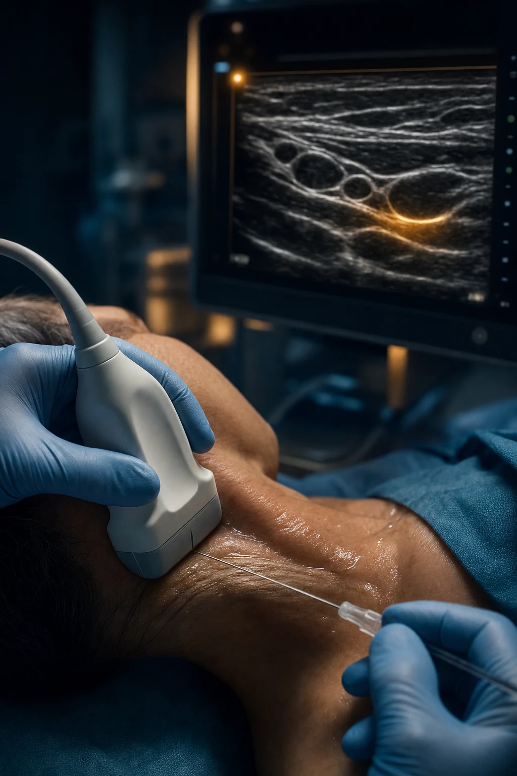
[1]Needle visualisation: the in-plane and out-of-plane approaches
The needle is introduced into the ultrasound field in one of two orientations relative to the probe, and the choice defines the whole technique of the block. The needle is a bright reflector (metal reflects sound strongly), and the problem in both approaches is to see the needle clearly and, above all, to know at every moment where the tip is[4][6].
The in-plane approach
In the in-plane approach the needle is inserted so that its entire length lies within the plane of the ultrasound beam — that is, the needle is parallel to the long axis of the probe. The whole needle, from skin entry to tip, is seen on the screen as a bright line, and critically the tip is seen in its exact relation to the nerve. This gives accurate tip localisation: the operator can see the tip pass beside the nerve, and can watch the local anaesthetic spread from the tip around the nerve. The advantages are the certainty of tip position and the ability to deposit the local anaesthetic precisely[4][8].
The in-plane approach is technically harder. The ultrasound beam is very thin — about one millimetre thick — and the needle must be kept exactly within this thin sheet of sound. A fraction of a millimetre of needle deviation to either side takes the needle out of the plane, and the needle vanishes from the screen. The approach typically requires a longer needle and a shallower insertion angle (about thirty to forty-five degrees from the skin), and the probe must be held rock-steady in the exact plane of the needle. The long path through tissue also means more tissue traversed and, for deep blocks, more difficulty keeping the whole needle in view[4][8].
The out-of-plane approach
In the out-of-plane approach the needle is inserted roughly perpendicular to the long axis of the probe, so that it crosses the ultrasound beam. The needle is seen not as a line but as a single bright dot — the cross-section of the shaft where it intersects the beam. The approach is ergonomically easier: the needle is often shorter, the angle steeper, and the technique is more forgiving of small movements, because the dot remains visible as long as some part of the needle is in the beam. Many operators find it the easier approach to learn[4][8].
The hazard of the out-of-plane approach is that the bright dot is the shaft, not necessarily the tip. The tip may have advanced beyond the beam and be lying unseen in the tissue ahead — potentially in a nerve or a vessel — while the operator, watching the dot, believes the needle is still at the beam. This is the central danger of out-of-plane needling, and it is the reason for the discipline of dynamic needle tip positioning and hydrolocation (below)[4][5].

The walk-off technique and hydrolocation
Because the out-of-plane dot may be the shaft rather than the tip, two techniques are used to ensure the tip is always known. [1]
The first is dynamic needle tip positioning, sometimes called the walk-off or slide technique. The probe is positioned so that the needle's bright dot is just visible at the near edge of the beam. The needle is then advanced a tiny amount — one or two millimetres — until the dot brightens and the tip is at the beam. Then the probe is slid a small distance in the direction of needle travel, so the dot disappears, and the needle is again advanced until the dot reappears. This cycle — slide the probe ahead, advance the needle to the beam — is repeated, so the tip is repeatedly re-acquired as the brightest point and is never advanced beyond the field of view. The tip is always the leading edge of the dot, never allowed to outrun the beam[4][8].
The second is hydrolocation (hydrodissection). A tiny bolus of fluid — one or two millilitres of saline or dextrose, or the local anaesthetic itself — is injected through the needle. If the tip is correctly placed, a bright (hyperechoic) bloom of fluid is seen to spread from the tip, often opening up the tissue plane around the nerve; this confirms both the tip's position and the fact that injection is possible (if no spread is seen, the tip may be intraneural or against dense tissue). The injected fluid also makes the needle tip easier to see, because the fluid-tissue interface is a strong reflector. Hydrolocation is the single most reliable bedside confirmation of tip position in the out-of-plane approach, and it should be used whenever the tip's relation to the nerve is in doubt[4][5].
[1]Needle design and visibility
Not all needles are equally easy to see. The visibility of a needle on ultrasound depends on its calibre (a larger needle reflects more sound), its material, its surface finish, and the angle at which it meets the beam. Specialty block needles are manufactured with textured or coated tips (echo-enhanced needles) specifically to scatter more sound back toward the probe and so to be more visible, particularly at steep angles where a smooth needle reflects sound away[6]. The angle of incidence matters: a needle perpendicular to the beam (the in-plane needle at a shallow angle) reflects sound back to the probe well, whereas a steep needle (the out-of-plane needle going almost straight down) reflects sound away and is poorly seen. Machine features such as beam steering, which angles the beam to meet the needle more perpendicularly, and needle-enhancement software improve visibility, but the operator's reliance on hydrolocation and on always watching the tip remains paramount[4][6].
Ergonomics: setting up for a precise hand-eye task
A regional block is a precise hand-eye task performed under time pressure, and like any such task it depends on the ergonomics of the setup. The evidence from eye-tracking and task-analysis studies is that experienced operators arrange the probe, the needle, the screen and themselves so that the whole procedure is visible without turning the head, and that this arrangement is itself a marker and a teacher of expertise[8].
Screen position
The ultrasound screen should be directly opposite the operator, at eye level, in the same line of sight as the operator's hands and the patient. The operator should be able to look at the screen and the procedure field by moving only the eyes, not by turning the head or the body. A screen placed to the side forces repeated head-turning that breaks the hand-eye loop, fatigues the operator and increases the risk of losing the needle. In the awake patient the screen can also be positioned so the patient can watch, which some find reassuring. [1]
The transducer grip
The probe is held like a pen, with the hand resting on the patient for stability. The heel of the hand, and where possible the little finger, are anchored on the patient's skin so that the probe moves only by deliberate finger action, not by arm movement. A probe held in the air by the arm alone is unstable: small muscle tremors translate into probe movement that loses the nerve. Anchoring the hand converts the probe into an extension of the fingers, and the deliberate, fine movements that sonoanatomy requires become possible. [1]
Needle insertion angle
The needle is inserted at the angle suited to the approach. For the in-plane approach a shallow angle (about thirty to forty-five degrees from the skin) keeps the needle within the thin beam and improves its reflection back to the probe. For the out-of-plane approach a steeper angle is common, but the steeper the needle the harder it is to see (the sound is reflected away), so the angle is a compromise between ergonomic ease and needle visibility. The needle is held by the non-scanning hand, which also aspirates and injects, while the scanning hand holds the probe. [1]
Operator position and team
The operator should be seated comfortably, with an armrest if available, positioned so that both the probe hand and the needle hand can reach their targets without stretching or leaning. The patient is positioned to expose the block site, prepped and draped in a sterile field, and an assistant manages the injection and watches the patient. A sterile probe cover and sterile gel are used for the block itself. The discipline of arranging all this before the needle is introduced — the screen, the seat, the patient position, the sterility, the assistant — is part of the block, not a preamble to it[8].

Artifacts: what fools the eye
An artefact is any feature of the image that does not represent a true anatomical structure. Artefacts arise because the machine makes assumptions — chiefly that sound travels in a straight line at a constant 1540 metres per second and reflects once — and when these assumptions are violated the image lies. Recognising the common artefacts is essential, because each can mislead the operator into injecting in the wrong place or missing a structure[2][3].
Acoustic shadowing
Acoustic shadowing is the dark region behind a strong reflector or absorber. Bone is the classic cause: the bright bone surface reflects almost all the sound, leaving a dark shadow beneath where nothing can be seen. Calcification (a calcified vessel wall, a calcified lymph node) and a strong ligament also shadow. Shadowing is useful as a landmark (identifying bone) but a hazard when a nerve lies behind bone: the nerve is invisible in the shadow, and the operator must angle the probe around the bone to see it. Shadowing also underlies the bright-line-and-shadow appearance that identifies bone[2][3].
Reverberation and the comet-tail artifact
Reverberation occurs when sound bounces back and forth between two strong reflectors — typically between the needle and the probe face, or between the two surfaces of a needle — so that multiple echoes return at progressively later times and are plotted at progressively greater depths, producing a series of bright parallel lines or a trailing tail of echoes below the true structure. The comet-tail (or ring-down) artefact is a form of reverberation seen as a bright line with a tapering train of echoes behind it, classically produced by the needle or by small gas bubbles or metal objects. Reverberation is the reason a needle can appear as a series of bright lines rather than a single line, and it can create the false impression of multiple needles or of a structure deeper than it is. The operator recognises it by its parallel, evenly spaced appearance and by its movement with the needle[2][3].
Anisotropy (revisited as an artefact)
Anisotropy, discussed above as a property of nerve and tendon, is also a pitfall: the darkening of a nerve when the beam is angled can make a nerve look like a hypoechoic vessel or make it disappear entirely. The correction is to tilt the probe to perpendicular, at which the nerve brightens, confirming its identity and restoring it to view[2][3].
Mirror-image artifact
A mirror-image artefact occurs when sound reflects off a strong smooth interface (classically the diaphragm or a bone surface) such that a structure on one side appears to be duplicated on the other side. In regional anaesthesia it is uncommon, but it can occur with the lung or a bone surface, creating the appearance of a structure where none exists. The artefact disappears when the probe angle is changed[2].
The bayonet artifact
The bayonet artefact is the apparent bending of a needle on the screen as it crosses a tissue interface where the speed of sound differs from the assumed 1540 metres per second. Because the machine assumes a constant speed, a region of slower or faster sound shifts the apparent position of the needle within it, making a straight needle look bent. It is a reminder that the image is a reconstruction based on an assumed speed of sound, not a literal picture[2][3].
Safety: the ALARA principle, the indices and sterile practice
Ultrasound is a form of energy delivered to the tissue, and although its clinical safety record over decades of use is excellent, the operator is bound by the principle of ALARA — as low as reasonably achievable — which means minimising the acoustic output and the exposure time while still obtaining a diagnostic image[2].
The mechanical index and the thermal index
Two indices are displayed on the ultrasound machine to quantify the risk. The mechanical index estimates the risk of mechanical bioeffects (chiefly cavitation — the formation and collapse of bubbles) from the peak negative pressure of the beam; it is kept below about 1.9 for diagnostic imaging. The thermal index estimates the rise in tissue temperature that the beam could cause; TIS (soft tissue), TIB (bone) and TIC (cranial) variants apply to different applications. For regional anaesthesia, where exposure times are short and the beam is not focused on a single point for long, both indices are usually well within safe limits, but the operator should keep them as low as the image allows and should not dwell on one spot unnecessarily[2].
Practical safety: ALARA in practice
The practical application of ALARA in regional anaesthesia is to use the lowest output power that gives a clear image (the gain and output are not the same — gain amplifies the returning echo, output increases the emitted energy), to minimise the time the probe spends on the patient, and to focus the beam at the target. The equipment is inspected before use (the probe and cable undamaged, the machine functioning), the probe cover is checked for integrity, and the sterility of the field is maintained throughout. For an aseptic block a sterile probe cover and sterile coupling gel are used, and the probe is sheathed before it touches the sterile field[5].
The two feared injuries: intraneural and intravascular injection
The two feared injuries of regional anaesthesia are intraneural injection (injecting local anaesthetic into the substance of a nerve, which can cause permanent nerve injury by mechanical disruption and pressure ischaemia) and intravascular injection (injecting into a vessel, causing local-anaesthetic systemic toxicity, LAST). Ultrasound is the principal safeguard against both, but only if its information is acted upon[5].
An intraneural injection appears on the screen as an expanding hypoechoic mass within the nerve as the local anaesthetic is forced into the nerve substance — the nerve swells. The injection should be stopped at once, the needle withdrawn, and the nerve re-imaged; an awake patient may also report severe pain. The defences are to keep the tip visualised, to inject slowly in small increments, to watch the spread, and to stop if the nerve swells or if injection is high-pressure or painful[5].
An intravascular injection is signalled by the local anaesthetic disappearing into a vessel rather than spreading around the nerve, and clinically by the symptoms and signs of LAST (perioral tingling, agitation, progressing to seizures and cardiovascular collapse). The defences are to identify all vessels with Doppler before injecting, to aspirate before and during injection, to inject slowly in small increments watching the spread, and to have lipid emulsion immediately available. The principle that unifies both is: always know where the tip is, and always watch the spread[1][5].
The clinical workflow of an ultrasound-guided block
The block itself follows a disciplined sequence that applies the foregoing principles. The operator first sets up the ergonomics (screen, seat, patient position, sterility, assistant) and chooses the probe for the depth of the target. The target region is scanned without the needle: the nerve is identified and confirmed (honeycomb texture, course, anisotropy, relation to vessels confirmed by Doppler and to fascial planes and bone), the adjacent structures are named (the vessels that must be avoided, the bone landmarks, the pleura or peritoneum that must not be crossed), and the depth, focus and gain are set to centre the target at its brightest[1][2].
Only when the sonoanatomy is clear is the needle introduced, in the chosen in-plane or out-of-plane approach, and only when the tip is seen is it advanced. The tip is brought to the intended injection point — beside the nerve, within the fascial plane — and its position is confirmed, by hydrolocation in the out-of-plane approach. After aspirating to exclude intravascular placement, the local anaesthetic is injected slowly in small aliquots, and the spread is watched: a correct spread is a hyperechoic halo of fluid surrounding the nerve or distending the fascial plane; an incorrect spread is fluid ballooning within the nerve (intraneural) or disappearing into a vessel (intravascular). The needle is repositioned as needed to ensure the local anaesthetic surrounds the nerve circumferentially, and the dose is kept to the minimum that produces the block[1][5].
[1]Ultrasound versus nerve stimulation: the modern practice
Before ultrasound, the nerve stimulator was the principal tool for localising a nerve. A stimulating needle delivered a current (typically starting at about one milliampere and reduced as the nerve was approached) that depolarised the nerve and produced a motor response (a twitch) in its distribution; the current threshold at which the twitch persisted (about 0.2 to 0.5 milliampere) was taken to indicate proximity to the nerve. The stimulator is an indirect, functional method: it infers the nerve's position from the motor response it evokes, and it works only on motor or mixed nerves (a pure sensory nerve does not twitch)[7].
Ultrasound is a direct, anatomical method: it shows the nerve, the needle and the spread in real time. A systematic review and meta-analysis comparing ultrasound with electrical stimulation found that ultrasound improved the success rate of peripheral nerve blocks, reduced the risk of vascular puncture, and shortened the onset time, although the magnitude of benefit varied by block[7]. The advantages of ultrasound are the direct visualisation of the nerve (important when the anatomy is altered by surgery, obesity or variation), the identification and avoidance of vessels and other structures, the ability to see the local anaesthetic spread around the nerve (and so to detect intraneural injection and to use smaller volumes), and the applicability to pure sensory nerves that do not respond to stimulation[1][7].
The stimulator retains roles. It provides a functional confirmation that the bright structure seen on ultrasound is indeed the nerve (a motor twitch at low current confirms identity), it can be useful in deep blocks where ultrasound resolution is poor, and it is a fallback when ultrasound is unavailable. The modern consensus is that ultrasound is the primary tool and the stimulator an adjunct: many practitioners use both together (the dual-guidance technique), with ultrasound for the anatomy and the stimulator for functional confirmation, but the standard of care for most peripheral blocks is ultrasound first[1][5][7].
The learning curve and education
USGRA is a hand-eye skill, and like all such skills it is acquired through deliberate practice. The learning curve varies by block — a superficial block such as the interscalene or the femoral may be learned in a modest number of cases, while a deep block such as the psoas compartment or the subgluteal sciatic requires more. Phantoms (gel, tofu, turkey breast models) and simulators allow the needle-probe coordination to be practised without a patient, and structured courses and supervised practice are the route to competence. Eye-tracking studies have shown that as expertise develops the operator's gaze is distributed more efficiently between the screen and the procedure, and that gaze pattern is both a marker of expertise and a target of training[8].
The ASRA practice advisory and the training literature emphasise that the prevention of neurologic complication rests not on any single device but on the disciplined application of the whole technique: the right probe, the optimised image, the visualised tip, the watched spread, the aspiration, and the willingness to stop and reposition when the picture is wrong. The machine is only as safe as the operator using it[5].
Common traps
Candidates and trainees commonly fall into a small number of traps. The first is choosing the wrong probe — a high-frequency probe for a deep target, or vice versa — and concluding that the nerve cannot be seen when the real problem is the physics of penetration or resolution. The second is failing to recognise anisotropy: searching for a dark, angled nerve when tilting the probe to perpendicular would reveal it bright and clear. The third is the out-of-plane dot: advancing on a bright dot that is the shaft, not the tip, and so advancing the tip blindly beyond the beam. The fourth is mistaking a vessel for a nerve (or a nerve for a vessel) and not applying Doppler and the compressibility test. The fifth is injecting without watching the spread, and so missing an intraneural swelling or an intravascular disappearance of the injectate. A strong answer to any viva or SAQ on this topic names each trap and the corrective discipline[2][3][4][5].
DR SOAK — the six pitfalls of ultrasound-guided blocks
Summary
Ultrasound-guided regional anaesthesia is the standard of modern practice because it lets the operator see the nerve, the needle and the spread in real time, and so deliver the local anaesthetic precisely while avoiding the two feared injuries of intraneural and intravascular injection. Its mastery rests on three layers: the physics of the piezoelectric crystal, the pulse-echo principle and the resolution-penetration trade-off of probe frequency; the sonoanatomy of the echogenic tissues and the artefacts that can fool the eye; and the technique of the in-plane and out-of-plane needle approaches, the discipline of always knowing where the tip is, and the ergonomics and safety framework that let the operator perform the block well. The modern practice is ultrasound first, with the nerve stimulator as an adjunct for functional confirmation, and the standard of care for most peripheral blocks is now image-guided[1][5][7].
Red flags
References
- [1]Marhofer P, Greher M, Kapral S Ultrasound guidance in regional anaesthesia Br J Anaesth, 2005.PMID 15277302
- [2]Sites BD, Brull R, Chan VW, et al. Artifacts and pitfall errors associated with ultrasound-guided regional anesthesia. Part II: a pictorial approach to understanding and avoidance Reg Anesth Pain Med, 2007.PMID 17961842
- [3]Sites BD, Brull R, Chan VW, et al. Artifacts and pitfall errors associated with ultrasound-guided regional anesthesia: Part II: A pictorial approach to understanding and avoidance Reg Anesth Pain Med, 2010.PMID 20216030
- [4]Chin KJ, Perlas A, Chan VW, Brull R Needle visualization in ultrasound-guided regional anesthesia: challenges and solutions Reg Anesth Pain Med, 2008.PMID 19258968
- [5]Neal JM, Barrington MJ, Brull R, et al. The Second ASRA Practice Advisory on Neurologic Complications Associated With Regional Anesthesia and Pain Medicine: Executive Summary 2015 Reg Anesth Pain Med, 2015.PMID 26288034
- [6]Maecken T, Zentai D, Saporoschenko I, Thomas M Ultrasound characteristics of needles for regional anesthesia Reg Anesth Pain Med, 2007.PMID 17961844
- [7]Munirama S, McLeod G A systematic review and meta-analysis of ultrasound versus electrical stimulation for peripheral nerve location and blockade Anaesthesia, 2015.PMID 25989611
- [8]Owen RL, Flavin S, Zuckerman LM, Hadzic A Tale of two approaches to ultrasound-guided interscalene brachial plexus block: a pro-con Reg Anesth Pain Med, 2025.PMID 40555526
- [9]Puma A, Caro AA, Paves G, et al. Ultra-high-frequency ultrasound imaging of sural nerve: A comparative study with nerve biopsy in progressive neuropathies Muscle Nerve, 2021.PMID 32939798