ICU · Equipment & physics
Equipment & Physics — Gas Laws, Measurement, Ventilators, Circuits and Monitors
Also known as Equipment and physics · Gas laws · Measurement physics · Ventilator physics · Breathing circuits · Pulse oximetry · Capnography · Defibrillator · Pressure transducer
The equipment and the physics of the ICU — the gas laws (the Boyle, the Charles, the Gay-Lussac, the universal gas law, the Dalton, the Henry, the Graham/Fick diffusion, the critical temperature), the measurement physics (the pressure transducer and the Wheatstone bridge, the thermistor, the Clark electrode for the oxygen, the Severinghaus for the CO2, the paramagnetic and the infrared analyzers), the pulse oximetry (the 660/940 nm and the limitations), the capnography (the infrared and the waveform), the temperature monitoring, the ventilator (the classification, the control, the drive, the breathing system, the valves), the breathing circuits (the circle, the Mapleson, the CO2 absorber), and the defibrillator (the monophasic vs the biphasic).
On this page & tools
Your progress
Saved locally on this device.
5 MCQs with explanations
Target exams
Overview & definition
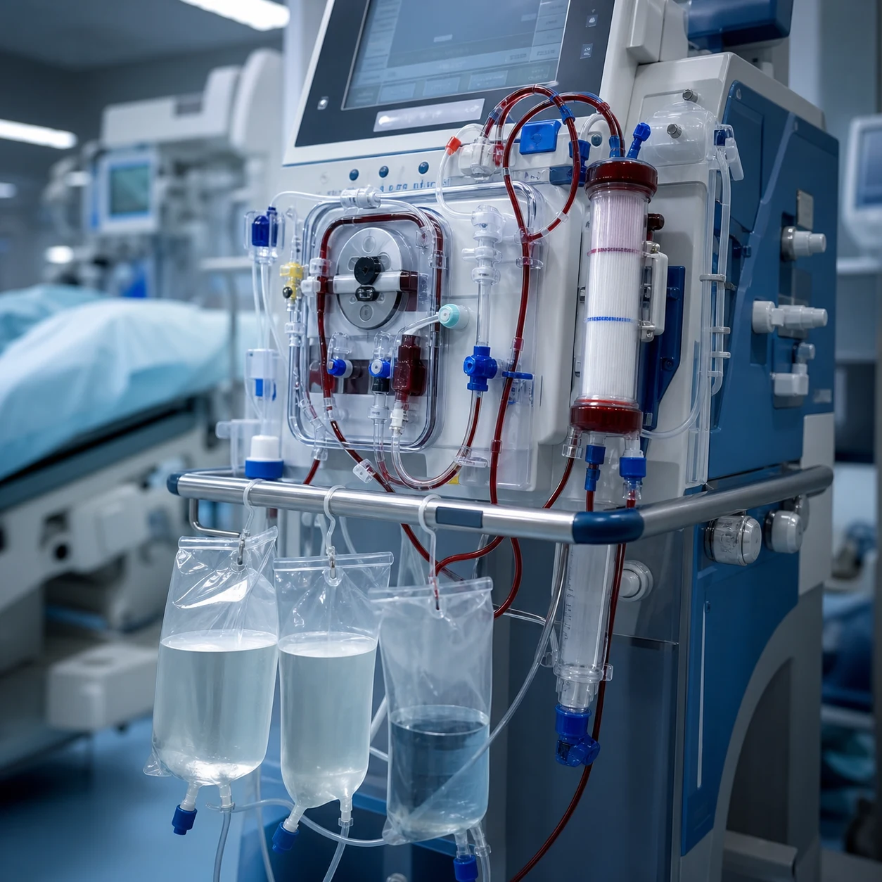
The equipment and the physics is the CICM First Part backbone — the gas laws, the measurement physics, the ventilator, the breathing circuits and the monitors that the intensivist uses daily. The examinable content: the gas laws, the measurement physics (the transducers, the electrodes, the analyzers), the pulse oximetry, the capnography, the temperature monitoring, the ventilator, the breathing circuits, and the defibrillator.[1][1]
The gas laws
The gas laws relate the pressure, the volume and the temperature of a gas. They are the foundation of the gas physics.[1]
- The Boyle law — at the constant temperature, the pressure and the volume are inversely proportional (the P1V1 = P2V2). The clinical relevance: the gas volume falls with the depth (the diving), the squeeze of the gas in the compliance.
- The Charles law — at the constant pressure, the volume is proportional to the absolute temperature (the V1/T1 = V2/T2). The relevance: the gas expansion with the warming.
- The Gay-Lussac law — at the constant volume, the pressure is proportional to the temperature (the P1/T1 = P2/T2).
- The universal (the ideal) gas law — the PV = nRT, combining the three. The relevance: the moles of gas, the cylinder content.
- The Dalton law — the total pressure of a gas mixture is the sum of the partial pressures of its components. The relevance: the partial pressure of each gas (the oxygen at the 21 per cent of the 760 = 159 mmHg).
- The Henry law — at the constant temperature, the amount of a gas dissolved in a liquid is proportional to its partial pressure (the relevance: the dissolved oxygen, the nitrogen narcosis, the decompression sickness).
- The Graham law and the Fick law of diffusion — the diffusion rate is proportional to the solubility and inversely proportional to the square root of the molecular weight; the relevance: the CO2 diffuses 20 times faster than the oxygen (the high solubility, the low weight).[1][1]
The critical temperature is the temperature above which a gas cannot be liquefied however great the pressure. Below the critical temperature, the substance is a vapour (liquefiable); above, a gas. The nitrous oxide (the critical temperature of 36.5 degrees C) is a vapour at the room temperature (it liquefies in the cylinder); the oxygen (the critical temperature of minus 118 degrees C) is a gas at the room temperature.[1]
The measurement physics [1]
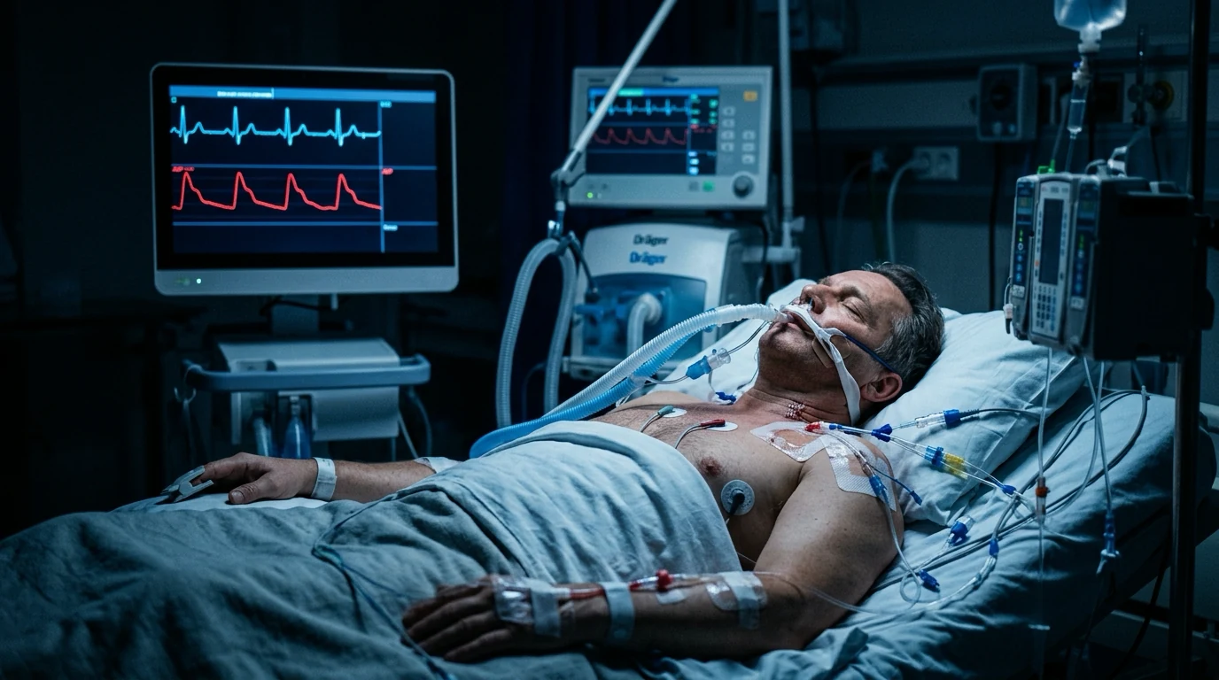
The ICU measurement converts a physical quantity (the pressure, the temperature, the gas concentration) to an electrical signal.[1]
The pressure transducer. The invasive blood pressure is measured by the strain-gauge transducer — the pressure deforms a diaphragm, the strain gauges in the Wheatstone bridge change the resistance, and the imbalance produces the voltage proportional to the pressure. The key principles: the zeroing (the atmospheric reference), the levelling (the transducer at the right atrium for the CVP, at the phlebostatic axis for the arterial), the damping (the over-damping flattens the systolic, the under-damping overshoots — the resonance), and the natural frequency (the resonance when the heart rate harmonics approach it).[1][1]
The thermistor and the thermocouple. The thermistor is the semiconductor whose resistance falls with the temperature; the thermocouple is the junction of two dissimilar metals producing the voltage proportional to the temperature. Both measure the core temperature (the pulmonary artery, the oesophagus, the nasopharynx, the bladder).[5]
The Clark electrode (the polarographic) measures the oxygen partial pressure — the oxygen diffuses across a membrane to the gold or the platinum cathode, reduced at the constant voltage, the current proportional to the PO2. The Severinghaus electrode measures the CO2 — the CO2 diffuses across a membrane into a bicarbonate solution, the pH change measured. The blood-gas analyser uses these (plus the pH glass electrode).[1]
The paramagnetic oxygen analyzer — the oxygen is paramagnetic (the attracted to a magnetic field, unique among the common gases); the analyser measures the paramagnetism. The infrared analyzer measures the CO2, the nitrous oxide and the volatile anaesthetics (the infrared absorption at the specific wavelengths). The fuel cell (the galvanic) measures the oxygen (the oxygen-driven current).[1]
The pulse oximetry
The pulse oximetry non-invasively estimates the arterial saturation. The principle: the two wavelengths (the red 660 nm and the infrared 940 nm) pass through the tissue; the oxyhaemoglobin and the deoxyhaemoglobin absorb differentially (the oxyhaemoglobin absorbs more infrared, the deoxyhaemoglobin more red). The photodetector measures the ratio, and the pulse-added absorption isolates the arterial component. The calibration curve converts the ratio to the saturation.[1][2]
- The accuracy falls at the saturation below 80 per cent and the poor perfusion (the vasoconstriction, the low output, the hypothermia) — the weak pulse.
- The skin pigmentation overestimates the saturation in the darker skin — the occult hypoxaemia (the systematic review confirms the higher missed-hypoxaemia rate).[3]
- The dyshaemoglobins — the carboxyhaemoglobin (the CO) is read as the oxyhaemoglobin (the falsely high), the methaemoglobin biases toward the 85 per cent.
- The nail polish, the ambient light, the motion artefact, the anaemia (the low signal), the venous pulsation.[1]
The capnography
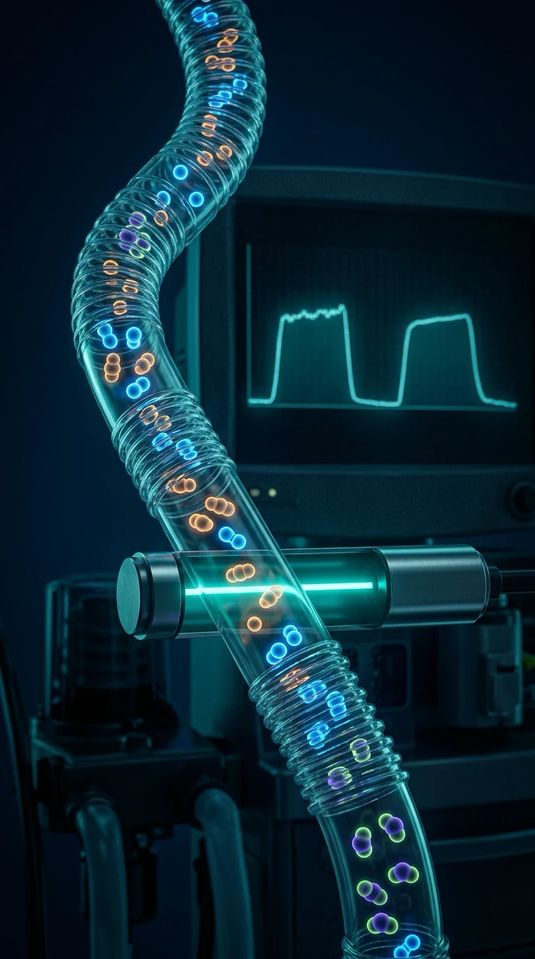
The capnography measures the exhaled CO2 by the infrared absorption. The time-based capnography (the CO2 over the time) shows the waveform; the volume-based (the CO2 over the exhaled volume) gives the anatomical dead space. The waveform has the four phases: the baseline (the dead space), the upstroke (the mixed dead space and the alveolar gas), the alveolar plateau (the peak is the end-tidal CO2), and the inspiratory downstroke.[4][1]
The clinical uses. The confirmation of the tracheal intubation (the continuous CO2 excludes the oesophageal intubation), the assessment of the cardiac output (the end-tidal CO2 falls with the low output — the CPR prognostication), the airway obstruction (the upsloping plateau — the COPD, the asthma), the disconnection, the malignant hyperthermia (the rising CO2 — the early sign), the rebreathing (the elevated baseline).[4][1]
The temperature monitoring
The core temperature is measured at the pulmonary artery (the most accurate), the oesophagus, the nasopharynx, the bladder and the rectum (the less accurate, the lag). The skin and the axillary are the peripheral (the poor). The perioperative temperature monitoring is the standard of care (the prevention of the hypothermia and its complications — the bleeding, the infection, the shivering).[5]
The ventilator
The ICU ventilator is the pneumatic and the electronic system that delivers the gas to the lung. The understanding of the ventilator is the First Part and the Second Part content.[1][1]
The classification.[1]
- The control variable — the pressure control (the pressure set, the volume variable) vs the volume control (the volume set, the pressure variable).
- The trigger — the time (the mandatory) or the patient (the pressure or the flow trigger).
- The cycle — the time (the pressure control), the volume (the volume control), or the flow (the pressure support).
- The mode — the CMV (the continuous mandatory), the SIMV (the synchronised intermittent mandatory), the PSV (the pressure support), the CPAP.
The components. The drive mechanism (the piston, the bellows, the turbine — the modern ICU ventilators use the microprocessor-controlled proportional valves), the gas-delivery system (the blending of the oxygen and the air), the breathing circuit (the inspiratory and the expiratory limbs, the humidifier, the filters), the expiratory valve (the PEEP control), and the monitoring (the pressure, the volume, the flow).[1]
The breathing circuits
The circle system (the anaesthesia and the modern ICU) — the unidirectional valves (the inspiratory and the expiratory), the CO2 absorber (the soda lime — the calcium hydroxide lime that absorbs the CO2, producing the heat and the water), the reservoir bag, the fresh-gas inlet, and the vaporiser. The circle allows the low fresh-gas flow (the economy, the warming, the humidification), and the rebreathing (the safety check for the CO2 absorber).[1]
The Mapleson circuits (the semi-open, the coaxial — the Bain is the Mapleson D) — the fresh gas, the reservoir bag, the adjustable pressure-limiting valve. The Mapleson classification (A to F) by the position of the components. The relevance: the transport ventilation and the scavenging; the Mapleson A is the efficient for the spontaneous, the D/E/F for the controlled ventilation.[1]
The CO2 absorber. The soda lime (the calcium hydroxide with the sodium and the potassium hydroxide activators, the silica binder) absorbs the CO2 — the indicator dye changes the colour (the white-to-purple or the pink-to-white). The hazards: the compound A (the sevoflurane — the low flow caution), the carbon monoxide (the desiccated absorbent with the volatile agents), the strong-base-free absorbents (the Amsorb) eliminate these.[1]
The defibrillator
The defibrillator delivers the direct current to depolarise the myocardium and terminate the fibrillation.[1]
- The monophasic (the damped sine, the obsolete) vs the biphasic (the current reverses mid-pulse — the lower energy, the higher success, the modern standard).
- The energy — the 150 to 200 J biphasic for the VF or the pulseless VT (the escalating).
- The transthoracic impedance — the chest-wall impedance (the 70 to 80 ohm); the reduced by the pads (the large, the correct position — the apex and the sternal-right), the gel, the shave, and the expiration.[1]
The pacemaker (the transcutaneous, the transvenous, the epicardial) delivers the electrical capture; the infusion pump (the syringe and the volumetric) delivers the precise drug infusion; the train-of-four monitor measures the neuromuscular blockade (the four twitches, the post-tetanic count).[1]
The equipment safety
The electrical safety — the macroshock (the large current through the body — the leakage, the earth fault), the microshock (the small current directly to the heart — the catheter, the 1 mA lethal). The equipotential earthing and the isolated patient circuits (the floating, the no direct earth) protect the patient. The MRI safety (the ferromagnetic projectiles, the implants, the burns from the conductive loops).[1]
Ventilator pneumatics — the engineering of gas delivery
The modern ICU ventilator is a dual-powered (pneumatic and electronic) microprocessor-controlled device. Understanding the pneumatic circuit — how gas is generated, conditioned, delivered, and exhaled — is core Fellowship content and the basis for troubleshooting every ventilator alarm.[1]
The gas source. The ventilator receives high-pressure oxygen (typically 345–414 kPa / 50–60 psi from pipeline, or 13 700 kPa / 2000 psi from a cylinder reduced by a regulator) and high-pressure air (pipeline at 414 kPa, or from an internal turbine/blower). Two architectures exist: (a) the pneumatic ventilator (Hamilton G5, Dräger Evita) — drives gas from external high-pressure sources through proportional valves; (b) the turbine ventilator (Maquet Servo-i, Vyaire Bellavista, Hamilton C3) — uses a high-speed impeller/turbine to generate flow from ambient air, with oxygen added downstream. Turbine ventilators are lighter, need no compressed-air pipeline, and dominate transport and NIV. [1]
The blender. The gas-blending module mixes oxygen and air to the set FiO₂. Two designs: (1) the mechanical mixer using a precision metering valve with proportional solenoids; (2) the microprocessor-controlled proportional valve that pulses oxygen into the air stream based on the measured FiO₂ feedback loop (response time 50–200 ms).[1]
The inspiratory valve. A proportional solenoid valve (or stepper-motor-driven poppet valve) that opens to deliver inspiratory flow. The microprocessor commands the valve aperture hundreds of times per breath to sculpt the pressure or flow waveform — the heart of the dual-control modes (PRVC, VC+, Autoflow). The valve must respond in <10 ms to track the set waveform. [1]
The expiratory valve. A pneumatic-mechanical pinch or diaphragm valve on the expiratory limb. It serves two functions: (1) releases exhaled gas to atmosphere (the expiratory phase); (2) imposes a resistance that generates PEEP. The microprocessor rapidly modulates the expiratory valve during expiration to maintain the set PEEP — if the valve sticks open, the patient loses PEEP and derecruits; if it sticks closed, the breath stacks (intrinsic PEEP, barotrauma). The expiratory valve is the most mechanically stressed component. [1]
The flow sensors. Two types: (a) the fixed-orifice differential-pressure flowmeter — a resistive element (mesh screen, venturi, or Fleisch tube) creates a pressure drop proportional to the square of the flow; two pressure taps feed a transducer and the flow is calculated. Robust, cheap, but non-linear at low flows. (b) The hot-wire anemometer — a heated platinum-tungsten filament is cooled by the gas flow; the electrical current needed to maintain temperature is proportional to flow (King's law). Highly accurate, linear, directional (with two wires), but fragile and drifts with humidity, so it is heated and the zero checked. Located in both inspiratory and expiratory limbs for the volume-balance check (VI − VE).[1]
The pressure transducer. A silicon piezoresistive or strain-gauge transducer converts the airway pressure to an electrical signal. Located at the ventilator outlet and at the expiratory valve. The transducer is zeroed to atmospheric pressure at startup and periodically (every 8–24 h) — drift causes the displayed Ppeak, Pplat, and PEEP to be wrong. The difference between the two transducers confirms the circuit integrity.[1]
The blower/turbine. In turbine ventilators a high-speed brushless DC motor drives a centrifugal impeller at up to 70 000 rpm, generating flow up to 250 L/min and pressure to 200 cmH₂O. The turbine is oil-free, maintenance-light, and decoupled from the hospital pipeline (useful in MRI-adjacent zones and on transport), but it draws in ambient air and so requires a fine inlet filter (HEPA) and is noisy (50–60 dB). On power loss a turbine ventilator fails to ambient pressure (the patient can breathe spontaneously through the circuit), unlike a pneumatic ventilator which can run on battery and pipeline.[1]
The safety and alarm architecture. (1) An inspiratory-pressure limit (set ~10 cmH₂O above Ppeak) — reaching it terminates inspiration and opens the expiratory valve (over-pressure protection). (2) An apnoea backup — switches to mandatory ventilation after a set apnoea interval. (3) A disconnect alarm — the expiratory flow drops below threshold; sensitive to leaks around the tube. (4) Gas supply alarms — low O₂ or air inlet pressure. (5) Power-failure switchover — battery backup and automatic mains/pipeline fail-over.[1]
The gas physics applied to ventilation
Each gas law has a concrete ventilator or respiratory correlate that is regularly examined.[1]
- The Boyle law (PV = constant at constant T). The lung is a Boyle-law device: the ventilator generates a pressure gradient (above or below atmospheric) and the lung volume changes inversely. Compliance (C = ΔV/ΔP) is the direct clinical expression. During controlled ventilation the alveolar pressure rises and the alveolar gas is compressed (the "compressible volume" of the circuit — ~3 mL/cmH₂O of pressure loss in adult circuits, more in paediatric). Cylinder contents: an oxygen cylinder at 13 700 kPa holds a fixed number of moles; as gas is drawn off the pressure falls proportionally (Boyle) so the cylinder pressure gauge directly indicates the remaining volume — unlike a nitrous-oxide cylinder which contains liquid and stays at constant pressure (the vapour pressure) until empty.
- The Charles law (V/T = constant at constant P). A warmed gas expands. The clinical correlate: gas delivered at 37 °C and fully saturated (47 mmHg water vapour) occupies a larger volume than the same dry gas at 22 °C. The BTPS correction (Body Temperature, Pressure, Saturated) is applied when converting spirometric volumes to body conditions — roughly a 10 per cent increase from ATPS (Ambient, Temperature, Pressure, Saturated). The humidifier and the HME both increase the delivered volume above the dry-gas set tidal volume.
- The Gay-Lussac law (P/T = constant at constant V). A fixed volume of gas rises in pressure as it warms. The clinical correlate: a sealed endotracheal tube cuff expands as the theatre warms (cuff-pressure creep), and a cylinder left in the sun rises in pressure.
- The universal gas law (PV = nRT). The molecular content of any container follows from this. The clinical correlates: (a) the cylinder-duration calculation — a 10 L water-capacity cylinder at 13 700 kPa holds (13 700 / 101.3) × 10 ≈ 1350 L of oxygen at atmospheric pressure; at 10 L/min flow it lasts ~135 min. (b) The cuff volume and the jet-ventilation gas calculations. R (the universal gas constant) is 8.314 J/(mol·K); T is in Kelvin.
- The Dalton law of partial pressures. The total pressure of a gas mixture is the sum of the partial pressures (Ptotal = ΣPᵢ). At sea level the dry atmospheric pressure is 760 mmHg — water vapour at 47 mmHg displaces dry gas, so the alveolar dry-gas pressure is 760 − 47 = 713 mmHg. The inspired partial pressures: PIO₂ = 0.21 × 713 = 150 mmHg; on 100 per cent oxygen, PIO₂ = 713 mmHg. The alveolar gas equation PAO₂ = PIO₂ − PACO₂/RQ is a direct application of Dalton's law (each gas exerts its own partial pressure independently). At altitude the atmospheric pressure falls and PIO₂ falls with it (Denver 1600 m, atmospheric ~630 mmHg, PIO₂ 0.21 × 583 = 122 mmHg).[1]
- The Henry law. The amount of gas dissolved in a liquid is proportional to its partial pressure (C = α × P, where α is the Bunsen solubility coefficient). Clinical correlates: (a) hyperbaric oxygen — at 3 atm, the dissolved oxygen in plasma (0.3 mL O₂/dL at 1 atm on 100 per cent O₂) rises to ~6 mL/dL — enough to sustain life without haemoglobin (treatment of CO poisoning, clostridial myonecrosis). (b) Decompression sickness — nitrogen dissolves in tissue at depth (Henry) and bubbles out on ascent (Boyle). (c) The CO₂ carriage in blood — CO₂ is 20-fold more soluble than O₂, which is part of why the venous-to-arterial PCO₂ gradient is small for a large content difference.[1]
- The Graham and Fick diffusion laws. The rate of diffusion is proportional to solubility and inversely proportional to the square root of the molecular weight. CO₂ (MW 44, highly soluble) diffuses 20× faster than O₂ (MW 32, less soluble) — the basis of the alveolar-capillary equilibration and the relative sparing of CO₂ exchange in pulmonary disease.
Humidification — the physics of water vapour
The upper airway warms, humidifies, and filters inspired gas to 37 °C and 100 per cent relative humidity (44 mg H₂O/L, 47 mmHg) — the isothermic saturation boundary is normally at the carina. An endotracheal or tracheostomy tube bypasses the upper airway, so dry medical gas (cylinder and pipeline gas is dry — <1 per cent humidity) delivered directly to the carina denudes the mucociliary escalator, inspissates secretions, and causes mucosal ulceration and atelectasis. Humidification is mandatory for any patient intubated for more than a brief period.[1]
Absolute humidity (AH) is the mass of water vapour per unit volume of gas (mg/L). Relative humidity (RH) is the ratio of the actual water-vapour pressure to the saturated water-vapour pressure at that temperature (× 100 per cent). The maximum water-vapour pressure rises steeply with temperature (the Clausius–Clapeyron relation) — at 20 °C the saturation pressure is 17.5 mmHg (RH 100 per cent = 17 mg/L); at 37 °C it is 47 mmHg (RH 100 per cent = 44 mg/L). A gas saturated at room temperature holds only ~40 per cent of the water needed at body temperature — if delivered to the lung it will steal the remaining 60 per cent from the mucosa. [1]
The heat and moisture exchanger (HME). A passive device — a hygroscopic paper, foam, ceramic, or a hydrophobic membrane impregnated with calcium chloride or lithium chloride, mounted in a housing between the catheter mount and the breathing circuit. On expiration it captures the heat and the water vapour of the alveolar gas (37 °C, 100 per cent RH); on inspiration the dry gas passing through recovers some of that moisture and warms. A modern HME returns 25–33 mg/L of water (70–80 per cent efficiency at 1 h), sufficient for short-term ventilation. Advantages: simple, no power, no water, low dead space (50–90 mL for adult HMEs), cheap, low infection risk (single-use, filter integrated). Disadvantages: (a) adds dead space — for a 7 mL/kg tidal volume the HME dead space may be 30–50 per cent of the tidal volume, doubling the required minute ventilation in the lung-protective range and unacceptable in hypercapnia or ARDS; (b) particulate obstruction — a saturated or sputum-loaded HME obstructs the circuit (a cause of sudden high peak pressure); (c) does not work in severe leaks (NIV with high leak); (d) contraindicated in frothy or bloody secretions, very small tidal volumes, or prolonged ventilation requiring high humidification.[1][1]
The heated humidifier (HH). An active device — a water-reservoir chamber on a heated plate, a heated wire in the inspiratory limb, and a temperature probe at the Y-piece. The water is heated to 37–40 °C and the gas leaving the chamber is fully saturated; the heated wire prevents rainout (condensation) on cooling through the inspiratory limb. A typical adult setting: chamber 37 °C, Y-piece 37 °C (or chamber 40 °C, Y-piece 37 °C to allow a small gradient and limit rainout), delivering 44 mg/L at 100 per cent RH. Advantages: (a) fully physiologic humidification; (b) no dead space; (c) usable in any leak or NIV; (d) preferred for prolonged ventilation, thick secretions, and small tidal volumes (ARDS, paediatric). Disadvantages: (a) risk of over-humidisation/overheating (rare thermal injury to the airway, water-loading of the lung if the circuit floods); (b) infection risk — the reservoir can grow Pseudomonas, Legionella if the water and the chamber are not changed per protocol (single-use sterile water, 24–48 h chamber change); (c) needs power and monitoring; (d) more expensive. [1]
Choice. HME for short-term (<96 h), low-risk ventilation with adequate reserve. Heated humidifier for: ARDS/lung-protective (small tidal volume), high minute ventilation/hypercapnia, thick or bloody secretions, prolonged ventilation, NIV with high leak, and any patient where HME dead space is detrimental.[1]
Oxygen delivery systems
The oxygen chain — from production to the alveolus — is the most safety-critical gas system in the ICU.[1]
The cylinder. Compressed gas in a high-pressure steel or aluminium (lighter, MRI-safe) cylinder, colour-coded by international convention (oxygen is white shoulder in ISO 32; in the US green, in ANZ white-on-black). A size E cylinder (water capacity 4.7 L) at 13 700 kPa (2000 psi) holds ~640 L of gaseous oxygen; a size G (46 L) holds ~6800 L; a size H/K (50 L) holds ~6900 L. A pressure-reducing valve drops the cylinder pressure to a working 414 kPa (60 psi) feeding the flowmeter or the ventilator. The cylinder pressure gauge falls linearly with content (Boyle's law) — multiply the cylinder pressure (in kPa) by the water capacity (in L) and divide by 101.3 to get the remaining volume in L. The pin-index safety system prevents the connection of an oxygen cylinder to a nitrous-oxide yoke. Cylinder contents should be checked before any transport; a size E at 10 L/min lasts ~60 min — always take a backup.[1]
The oxygen concentrator. A pressure-swing adsorption (PSA) device — a zeolite bed that preferentially adsorbs nitrogen at high pressure and releases it at low pressure. Two beds cycle (one adsorbing, one desorbing, ~10–20 s cycle) to deliver 90–96 per cent oxygen at up to 10 L/min (stationary) or 0.5–3 L/min (portable). Concentrators are cheap to run (only electricity), have no cylinder logistics, but deliver lower FiO₂ (90 per cent vs 100 per cent), are noisy, and the output falls if the sieve is contaminated by water. Used in ICU as a backup, in low-resource settings, and for long-term domiciliary oxygen. A liquid oxygen reservoir (LOX) is an alternative for domiciliary use — a 25 L LOX dewar holds the equivalent of ~25 000 L of gaseous oxygen.[1]
The pipeline. The hospital piped medical gas system (PMGS) supplies oxygen, air, and nitrous oxide from a central source (a manifold of J cylinders with auto-changeover, a liquid-oxygen VIE — Vacuum Insulated Evaporator — for large hospitals, or an oxygen plant). The pipeline (copper, medical-grade, oil-free brazed) runs at 414 kPa (60 psi) to gas-specific, non-interchangeable wall outlets (NIST — Non-Interchangeable Screw Threaded; DISS in the US; SIS — Socket Specific). The gas-specific probe on the hose mates only with the matching outlet — the engineering safeguard against wrong-gas delivery. The oxygen pipeline is the single point of failure for the whole hospital — a pipeline failure is a major incident with mortality.[1]
The wall outlet and the flowmeter. The flowmeter (a Thorpe tube — variable-area rotameter, or a digital electronic flowmeter) delivers a calibrated flow to the patient via the oxygen tubing. A humidifier (bubble or wick) may be added for low-flow oxygen. The flowmeter must be vertical (the rotameter float is gravity-dependent); tilting causes under-reading. The auxiliary oxygen outlet (high-pressure, direct from pipeline) feeds the ventilator and the high-flow devices. [1]
The oxygen analyser. An inline sensor (paramagnetic, galvanic fuel-cell, or polarographic) in the inspiratory limb of any mechanical ventilator — the only independent confirmation that the delivered FiO₂ matches the set FiO₂. The analyser must be calibrated to 21 per cent and 100 per cent before use; drift causes over- or under-reporting. A failing blender (a known failure mode) delivers an unknown FiO₂ — only the analyser detects this. [1]
Suction apparatus
The suction system removes secretions, blood, and debris from the airway and other body cavities. The components: (a) a vacuum source (central pipeline at ~−53 kPa, or a portable electric pump); (b) a vacuum regulator (adjusts the suction pressure — typically −80 to −200 mmHg for adults, −60 to −100 mmHg for paediatrics, −60 to −80 mmHg for neonates); (c) a collection bottle (1–3 L, disposable, with a safety overflow float valve); (d) the suction tubing; (e) the catheter (Yankauer for oropharynx, rigid; flexible catheters 10–18 Fr for endotracheal tube suction); (f) the bacterial filter on the exhaust (protects the vacuum pump and the environment).[1]
Closed-suction catheter. An in-line catheter enclosed in a sleeve, attached between the catheter mount and the endotracheal tube — permits suctioning without disconnecting the patient from the ventilator. Indications: high FiO₂, PEEP > 10 cmH₂O, severe hypoxaemia, ARDS, contagious respiratory infection (the closed system prevents aerosolisation). Advantages: no loss of PEEP, no desaturation, lower contamination risk, repeated use for 24–72 h. Disadvantages: adds dead space (~15–30 mL), the catheter sleeve can kink, more secretions pool around the tube.[1]
Wall suction vs portable. Wall suction is the first choice (reliable, high flow, no battery). Portable electric suction (Laerdal, Rescue) is for transport, the field, and the resuscitation trolley — must be charged and tested daily. [1]
Suction technique. Pre-oxygenase with 100 per cent O₂ for 30–60 s. Insert the catheter without suction (avoiding mucosal trauma) until resistance, withdraw 1 cm, apply intermittent suction while withdrawing (no more than 10–15 s total per pass). Saline instillation (0.9 per cent, 2–5 mL) is controversial — useful only for tenacious secretions, not routine. Limit suction pressure to the minimum effective — excessive pressure causes mucosal injury, hypoxaemia, and atelectasis. [1]
FlowSteps — the equipment checks for the ICU ventilator
Ventilator checks — the start-of-shift and pre-use check
- VISUAL CHECK OF THE VENTILATOR AND THE CIRCUIT — power on, mains and battery indicator; gas supplies connected and pressures > 350 kPa (pipeline) / cylinder full; circuit intact, no cracks, the water-trap drained; the HME or the heated humidifier fitted and primed; the CO₂ sample line and the oxygen analyser in line.[1]
- SELF-TEST — run the automated self-test (most modern ventilators): the leak test, the compliance test, the occlusion test, the alarm test. The ventilator refuses to start if a critical test fails.
- CIRCUIT LEAK TEST — occlude the patient end, pressurise to 30 cmH₂O, the leak should be <100 mL/min (adult). A larger leak indicates a cracked circuit, a loose fitting, a leaking HME, or a faulty expiratory valve.
- ZERO THE TRANSDUCERS — zero the pressure and the flow sensors to atmosphere (drift causes erroneous Ppeak, Pplat, PEEP). Most ventilators do this automatically at startup and on a schedule.
- CALIBRATE THE O₂ ANALYSER — 21 per cent on room air, 100 per cent on pure oxygen. The O₂ analyser is the only independent check of the FiO₂.
- ALARM LIMITS — set the upper pressure limit (~10 cmH₂O above Ppeak), the apnoea interval (20 s), the low exhaled minute ventilation (80 per cent of set), the low/high FiO₂, the low PEEP.
- HUMIDIFIER — set the chamber temperature and the Y-piece temperature; check the water level and the refill system.
- CONNECT THE PATIENT — confirm the tidal volume delivered matches the set, the exhaled volume matches the inhaled (VI − VE <100 mL, larger = leak), the capnograph traces, the SpO₂ is reading, and the patient is synchronised.
SAQ — Gas laws applied to critical care
10 minutes · 10 marks
A CICM fellow is asked in a viva: `State the gas laws relevant to anaesthesia and critical care, and explain how each applies clinically.` Outline the four named laws and one practical example each.
SAQ — Defibrillator physics and biphasic waveforms
10 minutes · 10 marks
A 60-year-old man in ICU develops ventricular fibrillation. The team prepares to defibrillate. The trainee asks: `Why is the modern defibrillator biphasic, and what energy do we deliver?` Outline the physics and the algorithm.
Clinical pearls — the equipment-physics viva [1]
Compare tables
HME vs heated humidifier — head-to-head
| Feature | Heat and moisture exchanger (HME) | Heated humidifier (HH) |
|---|---|---|
| Mechanism | Passive — captures exhaled heat and moisture, returns on inspiration | Active — water reservoir heated to 37–40 °C, heated-wire inspiratory limb |
| Efficiency | 70–80 per cent (25–33 mg H₂O/L) | 100 per cent (44 mg H₂O/L at 37 °C) |
| Dead space added | 50–90 mL (adult) | None |
| Power required | None | Electricity, water reservoir |
| Infection risk | Low (single-use, integrated filter) | Higher (reservoir can grow Pseudomonas, Legionella; 24–48 h change) |
| Best for | Short-term (<96 h), stable, low-leak ventilation | ARDS/lung-protective, thick secretions, prolonged ventilation, NIV with high leak, paediatric |
| Contraindicated | Frothy or bloody secretions, small Vt, high minute ventilation, hypercapnia | — |
| Failure mode | Particulate obstruction (sudden high peak pressure) | Overheating, flooding the circuit |
| Cost | Low (single-use) | Higher (chambers, sterile water, monitoring) |
Pneumatic vs turbine ventilator — architecture
| Feature | Pneumatic ventilator (Dräger Evita, Hamilton G5) | Turbine ventilator (Servo-i, Vyaire Bellavista) |
|---|---|---|
| Drive | Proportional valves on high-pressure O₂ and air pipelines | High-speed impeller (up to 70 000 rpm) on ambient air |
| Compressed-air supply | Required (pipeline or external compressor) | Not required (draws ambient air) |
| Weight and portability | Heavier, fixed | Lighter, transport-capable |
| Noise | Lower (40–50 dB) | Higher (50–60 dB) |
| Power failure | Runs on battery + pipeline (PEEP preserved) | Fails to ambient pressure (patient breathes spontaneously, PEEP lost) |
| MRI compatibility | Limited (ferromagnetic valves) | Some MRI-conditional models |
| NIV performance | Moderate | Excellent (high leak compensation) |
Oxygen delivery devices — FiO₂ delivered
| Device | Flow | FiO₂ delivered | Best use |
|---|---|---|---|
| Nasal cannula | 1–6 L/min | 0.24–0.44 (~4 per cent per L/min) | Chronic hypoxaemia, comfort; high-flow variants deliver more |
| Simple face mask | 5–10 L/min | 0.40–0.60 | Acute hypoxaemia, short-term |
| Non-rebreather mask | 10–15 L/min | 0.60–0.90 (theoretical 1.0) | Acute severe hypoxaemia, trauma |
| Venturi mask | Set by the valve | Precise 0.24, 0.28, 0.31, 0.35, 0.40, 0.50 | COPD — precise FiO₂ |
| High-flow nasal cannula | 30–60 L/min | Up to 1.0 + PEEP effect | Moderate hypoxaemic respiratory failure |
| Non-invasive ventilation | — | Up to 1.0 | Cardiogenic pulmonary oedema, COPD exacerbation |
| Mechanical ventilator | — | Up to 1.0 | Severe respiratory failure |
Common ventilator alarms — cause and action
| Alarm | Likely cause | Immediate action |
|---|---|---|
| High peak pressure | Cough, kink, mucous plug, water in the circuit, HME obstruction, tension pneumothorax | Disconnect, suction, observe; if persists — chest exam, exclude pneumothorax |
| Low exhaled tidal volume | Leak (cuff, circuit, HME), disconnect, bronchopleural fistula | Check the circuit, the cuff pressure; inflate cuff; check for disconnection |
| Apnoea | Patient stops triggering, sedation, neurological event | Manual ventilation; check the trigger sensitivity; assess sedation |
| Low FiO₂ | Blender failure, low gas supply pressure, analyser drift | Check pipeline/cylinder pressures; manual FiO₂ check; calibrate analyser |
| Low PEEP | Leak, expiratory valve stuck open, circuit disconnect | Check circuit and valve; reconnect; assess for leak |
| High FiO₂ | Blender failure, analyser drift | Calibrate the analyser; reduce set FiO₂ if safe |
Key trials and evidence
Spinelli and Costanzo — humidification in mechanical ventilation (PMID 31033717)
Document type
Narrative review — a comprehensive update on humidification in critically ill adults
Scope
Mechanism, comparison of HME and heated humidifiers, indications, complications
Key finding
HMEs and heated humidifiers are broadly equivalent for short-term ventilation; heated humidifiers preferred for ARDS, prolonged ventilation, NIV with high leak, and where HME dead space is detrimental
Clinical bottom line
Choose humidification based on tidal volume and duration. Heated humidifiers for small-tidal-volume and prolonged ventilation; HMEs acceptable for short-term uncomplicated ventilation
Lacherade et al — HME vs heated humidifier for VAP prevention (PMID 16109987)
Document type
Multicentre randomised controlled trial — the largest head-to-head
Population
369 ICU patients expected to be ventilated >48 h
Intervention
HME vs heated humidifier, primary outcome VAP
Result
No significant difference in VAP (HME 16 per cent, HH 19 per cent), ICU length of stay, or mortality. Subgroup with <7 days ventilation favoured HME
Clinical bottom line
Humidification choice does not change VAP risk; base the decision on dead space, secretion load, and duration rather than infection prevention
Subirana et al — HME vs heated humidifier meta-analysis for VAP (PMID 18820148)
Document type
Meta-analysis of 11 RCTs (n ~2000)
Intervention
HME vs heated humidifier in mechanical ventilation
Result
No significant difference in VAP, mortality, or ICU stay. Earlier reviews suggesting benefit of HME were not confirmed in the updated meta-analysis
Clinical bottom line
No infection-prevention rationale to prefer one humidifier over the other; the choice is physiological
Sessler — pulse oximetry principles and limitations (PMID 26866435)
Document type
Comprehensive review — the definitive reference on pulse oximetry
Scope
The 660/940 nm principle, the calibration curve, the limitations (perfusion, pigmentation, dyshaemoglobins)
Key finding
Pulse oximetry is the standard of care but has systematic limitations — accuracy falls below SpO₂ 80 per cent, perfusion and pigmentation bias the reading, carboxyhaemoglobin reads falsely high
Clinical bottom line
The single best reference for the Fellowship viva on pulse oximetry. Confirm with an arterial blood gas in any uncertain or critical reading
Owen — defibrillator waveforms and energy (PMID 31314843)
Document type
Review of defibrillator physics and modern practice
Scope
Monophasic vs biphasic, transthoracic impedance, pad position, energy
Key finding
Biphasic defibrillation achieves higher first-shock success (~90 per cent) at lower energy (120–200 J) than monophasic (200–360 J); the second phase reduces impedance
Clinical bottom line
Biphasic 150–200 J is the modern standard. Higher energy is not necessarily better — impedance, pad position, and timing matter more
Red flags — additional
Prognosis
The equipment and the physics underpins the safe and the effective ICU practice. The pulse oximetry and the capnography are the standard of care — the failure to use them (the unrecognised oesophageal intubation, the occult hypoxaemia) is the preventable harm.[1][4][1]
Red flags
References
- [1]Moon K, et al. Pulse Oximetry-A Perioperative Perspective Diagnostics (Basel), 2026.PMID 42351472
- [2]Leon-Valladares D, et al. Determining factors of pulse oximetry accuracy: a literature review Rev Clin Esp (Barc), 2024.PMID 38599519
- [3]Cotton SA, et al. Do Differences in Skin Pigmentation Affect Detection of Hypoxemia by Pulse Oximetry: A Systematic Review of the Literature Clin Nurs Res, 2025.PMID 41045137
- [4]Ishihara T, et al. Time-Based Capnography to Diagnose Airway Obstruction During Lung Lobectomy in a Dog Animals (Basel), 2025.PMID 41375427
- [5]Jogie J, et al. Perioperative Temperature Monitoring in Anesthesia: A Review of Current Evidence and Clinical Practice Cureus, 2026.PMID 42147589
- [6]Yu H, et al. Depth of anesthesia monitoring: Current evidence, clinical impact, and future directions J Int Med Res, 2026.PMID 42333677
- [7]Huang X, et al. Effects of EEG-based monitoring of depth of anesthesia on postoperative delirium, cognitive dysfunction, and long-term neurocognitive outcomes: a meta-analysis Front Med (Lausanne), 2025.PMID 41907691